VRF lite is a feature that adds an additional identifier to each
prefix assigned to a VRF called a route-distinguisher. As the name suggests the
route-distinguisher (RD) provides an additional value to a prefix to
distinguish it from other routes in the global routing table. Essentially
creating multiple routing tables distinguishable by the RD. By assigning
interfaces to a VRF the prefixes whether they are connected, static, or
dynamically learned are assigned the VRF's RD and are stored separately in the
VRF's RIB and CEF is updated accordingly to allow proper routing and packet
switching. You can view each vrf's RIB with the following command:
R1#show ip route vrf vrf_name
In fact, for most information specific to a VRF such as assigned
interfaces or IGP/EGP information, it is necessary to use the vrf option in the
command to tell the cli that you are interested in information related to that
specific vrf. Today's lab will focus on this feature and how to configure it.
Concepts tested
- Configuring VRF'S
- Assigning interfaces to a VRF
- Configuring per VRF EIGRP address families
Complete the following tasks:
- Create loobpack1 interfaces on routers R1, R2, and R4 routers using IP x.x.x.x/32 where x is the router number for the given router. These IP's will overlap with the next task.
- Create loopback2 interfaces on routers R1, R2, and R3 routers using IP x.x.x.x/32 where x is the router number for the given router.
- Configure R1 to R4 communication through R2 using the subnets shown in the lab topology.
- Do not use any tunneling or overlay solution to accomplish this task
- Also configure R1 to communicate with R3 through R2 using the subnets shown in the lab
- Enable EIGRP to advertise R1,R2 and R4's loopback1 interface IP's with each other using only a single instance.
- Use the same EIGRP instance to advertise R1's, R2's, and R3's loopback2 address with each other.
- Confirm full connectivity between R1, R2, and R4 using the loopback1 addresses and do the same for R1, R2, and R3 for the loopback2 interfaces.
GNS3 configuration file, requires IOS v15 for the 7200 router: Link
Solution Below:
To begin create two VRF's on R1 and R2 so that R1-R4 addressing is
isolated from R1-R3 addressing. Create a unique route distinguisher (RD) in the
form of ASN:nn or ASN:x.x.x.x.

The last step of entering address-family mode and then exiting may
seem unnecessary but it's not. Doing so activates IPV4 for this VRF instance. If
you do not do this you will receive the following error when attempting to
assign the IPV4 addresses to a VPN_A VRF assigned interface.
Next assign interface Gig0/0 to VRF VPN_A and configure its IP address.
Now configure the same IP address on Gig 1/0, don't forget to no
shut each interface.
Without Gig0/0 being assigned to VRF VPN_A you would not normally
be able to assign the same IP address to two different non-point-to-point
interfaces. But because interface Gig0/0 is allocated to VRF VPN_A there is no
conflict.
Only interface Gig1/0 is in the global routing table.

Interface gig0/0 is in the VRF VPN_A routing table.

Now perform similar tasks on R2 to allow for the duplicate
addressing.


Now configure R2 to R3 and R2 to R4 addressing.


Something to point out here is that if your forget to use the VRF
forwarding command on interface s2/1 the cli will not complain about duplicate
subnets. This not the case with R1, if you had forgotten to apply the VRF
forwarding command before the IP address on Gig 0/0 you would have received an
error from the CLI similar to the one in the picture below. With R2 the command
is allowed because the interfaces are point-to-point and the default
encapsulation is HDLC.

If you look at the CEF table you will see the duplicate paths are
treated as load balanced paths. This is considered a valid configuration but is
more commonly seen with PPP/MPPP

Next we need to create our loopback addresses.


With all interface addressing out of the way we can move on to
enabling and configuring EIGRP.

Now let's look at what was done here. First we created a named
EIGRP process called VRF_LITE. With named EIGRP processes you can create and
modify multiple EIGRP instances based on addresses family and VRF association.
So with the first address-family command I am creating an IPV4 EIGRP instance
AS 1 for the global routing table. The second address-family I am create
another separate EIGRP instance AS 1 for the VRF VPN_A. Both instances operate
as separate EIGRP instances and they do not share an EIGRP topology table.
Now let's continue with our EIGRP configuration on R2,R3, and R4.

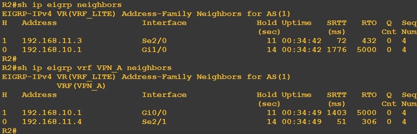
Now we see our neighbors come up
R3 and R4 our more conventional EIGRP configuration


Now we can look at our routing tables and neighbors to see if we
have missed anything


So far everything look pretty good. The final test is to confirm
connectivity between our loopbacks.


Looks goods, and that it!
No comments:
Post a Comment